Windows 10 for IoT on Raspberry Pi2 to control LEDs
In this article, we will connect three different colors LED to Raspberry Pi 2 with Windows 10 for IoT preloaded. The respective LED will light up corresponding to the button clicked.
Components:
- 1 x red LED
- 1 x yellow LED
- 1 x green LED
- 3 x 330Ω resistors
- 1 x HDMI TV/Monitor
- 1 x breadboard and serveral male-to-female connector wires
- 1 x Raspberry Pi 2 with loaded Windows 10 for IoT (If you want to know how to provision the Windows 10 for IoT to your Raspberry Pi 2, you can refer to this article
Hardware Setup
Let’s start by wiring up the components on the breadboard as shown in the diagram below.
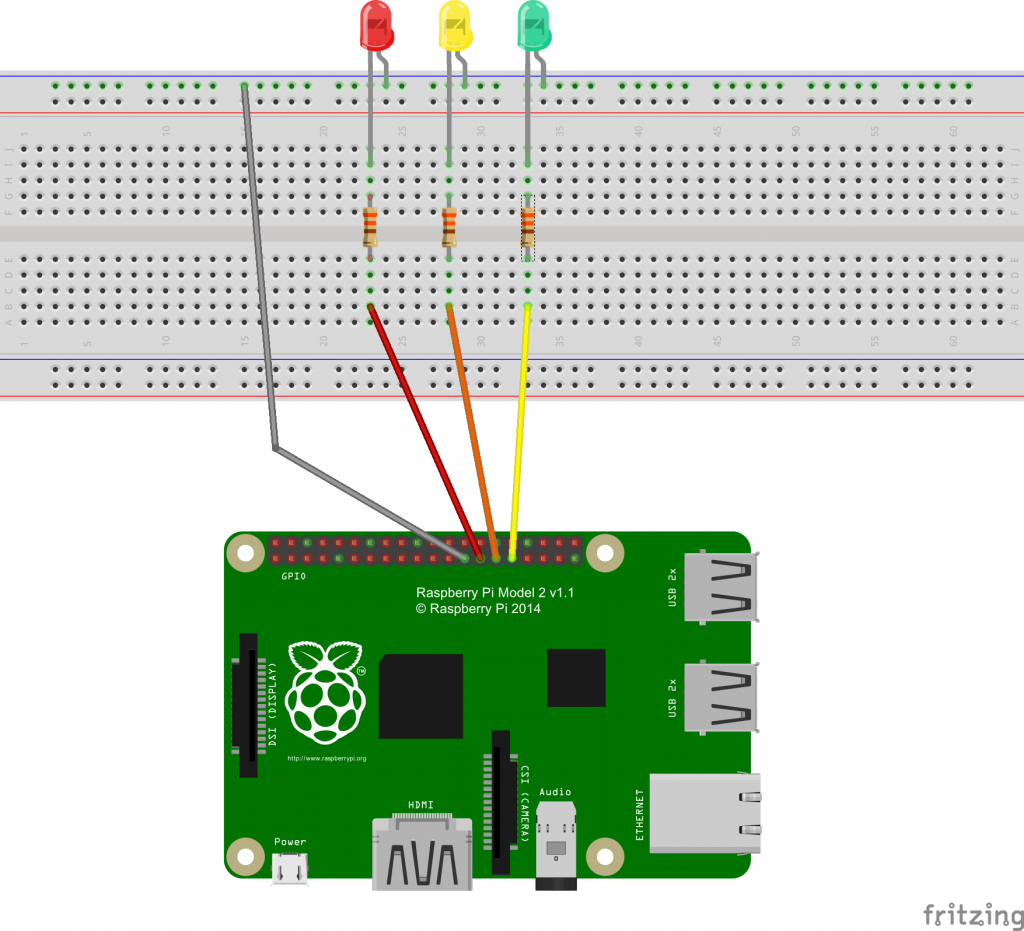
- Connect the cathode of the LEDs to the Ground rail of the breadboard using 330Ω resistors respectively.
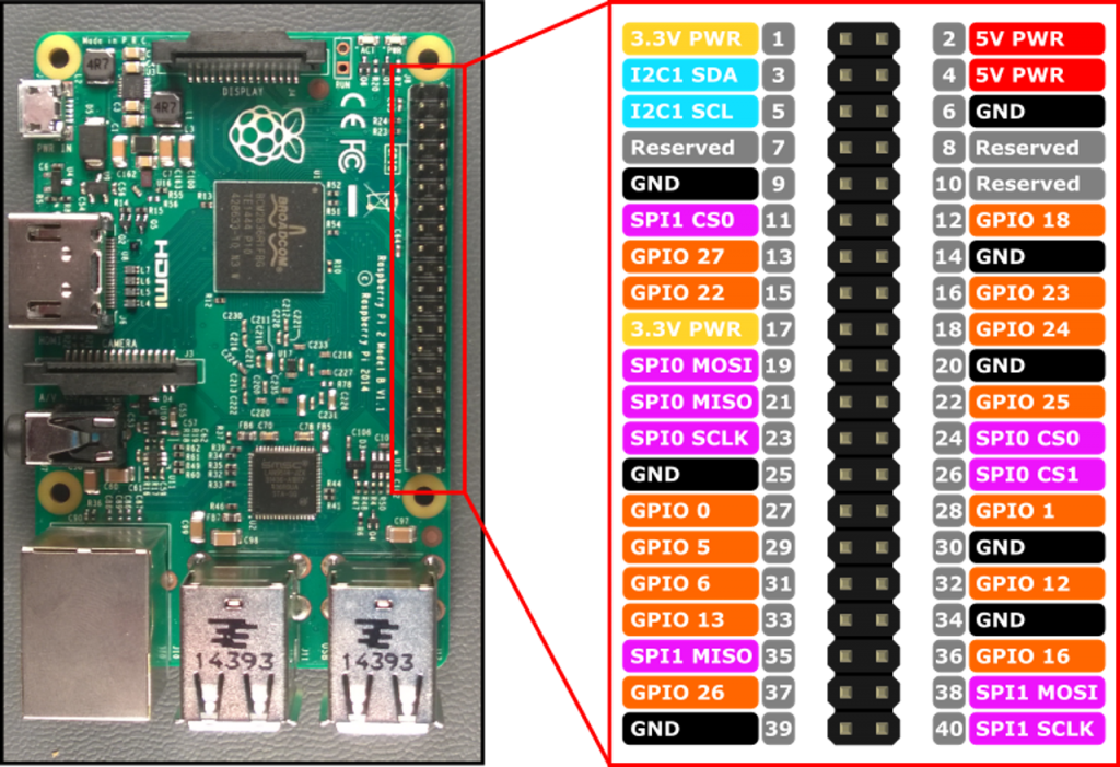
- Connect the anode of the LED to Pin 27 (GPIO 0) for Red LED, Pin 29 (GPIO 5) for Yellow LED and Pin 31 (GPIO 6) for Green LED.
- Pin 25 (GND) connect to ground rail on the side of the breadboard.
Create Sample App
You can download the entire sample code from GitHub.
The code in this sample does the following things:
- Initializes the Raspberry Pi 2 GPIO pins
- Responds to user input
a. Turn On and Off the LEDs
b. Turn Off all LEDs
Add content to MainPage.xaml
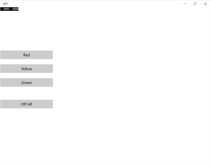
Let’s add some simple design to MainPage which will be displayed on a screen that connected to Raspberry Pi 2. We want to put total of 4 buttons and it will respond to the user clicks.
        <Button Name="redBtn" Content="Red" HorizontalAlignment="Stretch" Click="redBtn_Click" />
        <Button Name="yellowBtn" Content="Yellow" HorizontalAlignment="Stretch" Click="yellowBtn_Click" Margin="0,20" />
        <Button Name="greenBtn" Content="Green" HorizontalAlignment="Stretch" Click="greenBtn_Click" />

        <Button Name="clearBtn" Content="Off All" HorizontalAlignment="Stretch" Click="clearBtn_Click" Margin="0,50" />
    </StackPanel>
Add content to MainPage.xaml.cs
Before we add any code to MainPage.xaml.cs, we need to add Windows IoT Extension to our reference.
- In Solution Explorer, right click on References and select Add Reference…
- In the Reference Manager windows, click the arrow next to Windows Universal then click on Extensions
- Check the box next to Windows IoT Extension SDK and click OK
Add the following line at the top of MainPage.xaml.cs
using Windows.Devices.Gpio;With the references added, let put in the code.
The method of InitGPIO() does the following thing:
private void InitGPIO()
{
    gpio = GpioController.GetDefault();
    if (gpio == null)
      return;

    redpin = gpio.OpenPin(0);
    yellowpin = gpio.OpenPin(5);
    greenpin = gpio.OpenPin(6);
}- Initialized GPIO pins that going to use.
- Detect the presentation of GPIO.
The method of turnOffAllLED()
private void turnOffAllLED()
{
    redpin.Write(GpioPinValue.Low);
    redpin.SetDriveMode(GpioPinDriveMode.Output);

    yellowpin.Write(GpioPinValue.Low);
    yellowpin.SetDriveMode(GpioPinDriveMode.Output);

    greenpin.Write(GpioPinValue.Low);
    greenpin.SetDriveMode(GpioPinDriveMode.Output);

}- Set the value of respective pins value to ==Low==, this is similar to Arduino
digitalWrite(pinno, state)
Various button click method
private void redBtn_Click(object sender, RoutedEventArgs e)
{
    turnOffAllLED();
    redpin.Write(GpioPinValue.High);
    redpin.SetDriveMode(GpioPinDriveMode.Output);

    redBtn.Background = new SolidColorBrush(Colors.Red);
}
The codes above is to set the specific pin value to ==High== and committed the change. You can modified the redpin to yellowpin and greenpin.
Build, Deploy and have Fun!
Let’s build, deploy and run the app on Raspberry Pi 2.
You can refer to this article to learn how to deploy the app to Raspberry Pi 2.
Happy coding!